In this article, I will talk about my AHRS Estimation system, which I recently completed, using Quaternion and based on the MPU9250 sensor.
This system will also form the core of the AHRS system of my flight control board, Aldebaran.
What is AHRS?
AHRS stands for “Attitude and Heading Reference System”.
An AHRS consists of sensors on three axes that provide attitude information for aircraft, including roll, pitch and yaw. These are sometimes referred to as MARG (Magnetic, Angular Rate, and Gravity) sensors and consist of either solid-state or microelectromechanical systems (MEMS) gyroscopes, accelerometers and magnetometers. They are designed to replace traditional mechanical gyroscopic flight instruments.
The key difference between an inertial measurement unit (IMU) and an AHRS is the addition of an on-board processing system in an AHRS, which provides attitude and heading information. This is in contrast to an IMU, which just delivers sensor data to an additional device that computes attitude and heading. With sensor fusion, drift from the gyroscopes integration is compensated for by reference vectors, namely gravity, and the earth magnetic field. This results in a drift-free orientation, making an AHRS a more cost effective solution than conventional high-grade IMUs (Inertial Measurement Units) that only integrate gyroscopes and rely on a very high bias stability of the gyroscopes. In addition to attitude determination an AHRS may also form part of an inertial navigation system.
A form of non-linear estimation such as an Extended Kalman Filter is typically used to compute the solution from these multiple sources.
In this case, I’m using Quaternion based filter EKF to estimate AHRS

What is Quaternion?
There are lots of different definitions present for Quaternions, and they are varys on application.
If we talk about its use in AHRS systems, we use it to equate two different coordinate systems to each other, in the most “rough” terms. Here, the first is the plane’s coordinate system (this is also called the body frame), and the other is the coordinate system on which its navigation / movement depends. (It’s Earth. 🙂 )
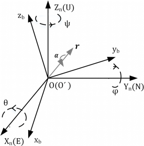
To explain in a little more detail, the orientation of a aircraft can be described by two coordinate frames. As shown in Figure 1, navigation frame (n frame) is organized by East-North-Up (ENU) definition. Let aircrafts right side as body frame (b frame) xb positive direction, forward as body frame yb positive direction and straight up as body frame zb positive direction. The origin of the b frame and n frame are aligned at point O. Hence, θ, ϕ, ψ represent pitch, roll and yaw angles respectively according to the Euler angles definition. A quaternion q is a ℜ4 vector that can be used to represent the orientation of b frame relative to n frame in ℜ3. An arbitrary orientation of b frame relative to n frame can be achieved through a rotation of angle α around the vector r in n frame.
Quaternion q is defined by:

Quaternion provides us with a way for rotating a point around a specified axis by a specified angle. If you are just starting out in the topic of 3D rotations, you will often hear people saying “use quaternion because it will have any gimbal lock problems”. This is true, but the same applies to rotation matrices well. Rotation matrices do not experience gimbal lock problems. In fact, it does not make sense to say that at all. The gimbal lock problem happens when you use Euler Angles, which are simply a set of 3 elemental rotations to allow you to describe any orientation in a 3D space. In attitude determination, we often visualize a 3D rotation as a combination of yaw, pitch and roll. These are Euler angles thus they are susceptible to the gimbal lock problem, regardless of whether you use quaternion or not.
Why Quaternions and Filtering Side
Sensor Fusion and Kalman Filters are usually the first thing that pops up for people like me who are just getting started. The use of the word “filter” can give the impression that a data is more accurate and more stable, which is both true and false.
However, as you can see in the title, I specifically used the word “estimation” instead of the word filter. Because using Quaternion doesn’t do much to improve the linearity or error rates of your IMu sensors.
We use the structure Quaternion, as I mentioned above, to adapt the aircraft’s body frame to the navigation body frame, that is, to the Earth. Because the IMU sensors are point-based, but the aircraft fly according to the Earth, that is, the attitude information changes according to the Earth. In this way, we can calculate the pitch yaw and roll values accurately and between the Earth and the plane. In this way, we can navigate our plane.
The Complementary Filter and Kalman Filter, which appear under Sensor Fusion, are quite similar to this, and they can even provide data filtering. However, both are linear systems, so they cannot be integrated into a 3D or non-linear system.

The accuracy, filtering or calibrating of the data coming from the IMU is another and important issue. Even the integrated or external Digital Low Pass Filters or the mean filter or the quality of the cable you connect the sensor can have an effect.
Here, for a healthy quaternion estimation, it is critical to calibrate the magnetometer and gyroscope, and also to calibrate the magnetometer with hard and soft iron type.
There is also a project that I designed using the MPU6050 and implementing the Kalman Filter. You can even get Pitch and Roll values using this code:
https://github.com/ibrahimcahit/STM32_MPU6050_KalmanFilter

Euler Angles and Gimball Lock
The Euler angles are three angles introduced by Leonhard Euler to describe the orientation of a rigid body with respect to a fixed coordinate system.
Euler angles are “degree angles” like 90, 180, 45, 30 degrees. Quaternions differ from Euler angles in that they represent a point on a Unit Sphere (the radius is 1 unit). You can think of this sphere as a 3D version of the Unit circle you learn in trigonometry. Quaternions differ from Euler angles in that they use imaginary numbers to define a 3D rotation.
Quaternions solve a problem known as gimbal locking. This occurs when the primary axis of rotation becomes collinear with the tertiary axis of rotation.


Conversion between Quaternions and Euler Angles
To get pitch, yaw and roll, we need to convert estimated quaternions to the Euler Angles.
A unit quaternion can be described as:

We can associate a quaternion with a rotation around an axis by the following expression:

where α is a simple rotation angle (the value in radians of the angle of rotation) and cos(βx), cos(βy) and cos(βz) are the “direction cosines” of the angles between the three coordinate axes and the axis of rotation.
To better understand how “direction cosines” work with quaternions:

If the axis of rotation is the x-axis:

If the axis of rotation is the y-axis:

If the axis of rotation is a vector located 45° (π/4 radians) between the x and y axes:

Therefore, the x and y axes “share” influence over the new axis of rotation.
The Euler angles can be obtained from the quaternions via the relations:

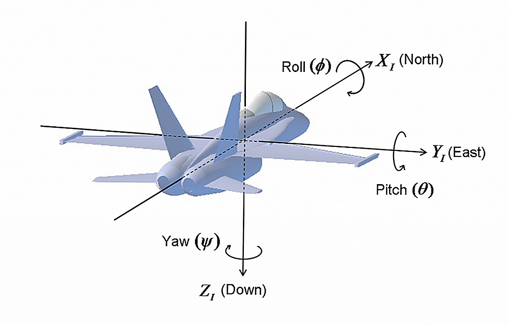
However, arctan and arcsin functions implemented in computer languages only produce results between −π/2 and π/2, and for three rotations between −π/2 and π/2 one does not obtain all possible orientations. To generate all the orientations one needs to replace the arctan functions in computer code by atan2:


Hardware and Setup
I used STM32’s newly G431 based G431RB Nucleo development kit. I also used MPU9250 (probably made in China) as the IMU sensor. For ease of use, I mounted the IMU sensor to the Nucle board with the plastic stand-offs I found.
The STM32G431 is a quite impressive card. It has 170 MHz clok speed, built-in ST-Link chip and FPU unit.

The MPU9250 is actually a combination of an MPU6050 and an AK8963 magnetometer. There are many example codes for simple connections on the Internet, even more than you would want for Arduino. 😀 But nothing for STM32.
Of course, it is not difficult to use with STM32, you just have to play with the registers, which is challenging until you get used to it if you are a beginner. But once you get used to it, it’s easier than using a ready-made library!
The IMU communicates using the I2C interface. So far I haven’t experienced any lag when using I2C. Besides, the code uses HAL_GetTick as timer. Although this timer, which returns in microseconds, is a timer that I wouldn’t want to use, I couldn’t implement the one works in milliseconds.
I used CubeIDE and C language to code. Also STMStudio to check the data and Hercules to get Debug from UART.
The Code
First starts with hardware initialization. Flow chart is below:

Each step, especialy calibration steps are crucial. You need to leave the system still when accel and gyro calibration begins; and need to draw 8 when magnetometer calibration begins. Calibrations are not a joke, they are crucial and if one of 9 axis calibration will wrong, whole system will be unusable.
After those steps, we are ready to read sensors and estimate attitude!
There are two sub-steps in here: Reading the data array from the sensor and calibrating with the calibration data; and calculating Quaternions using calibrated sensor data and then, calculating Pitch Yaw and Roll angles.

After reading and scaling/calibrating IMU data, we are ready to calculate Quaternions.

GitHub Repository
https://github.com/ibrahimcahit/MPU9255-Quaternion-AHRS-STM32
3D Visualising
Demo 1
Demo 2
Conclusion
Quartenion-based AHRS systems are the most widely used solution, especially in autonomous systems and autonomous UAVs. I think this application that I made with MPU9250 will be useful to many people.
Thank you for reading.
